3. How to compile the valve model No.?
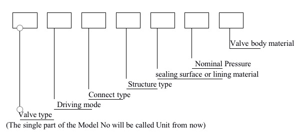
A. Introduction for the first Unit: Valve Type:
| Valve Type | Code |
| Gate Valve | Z |
| Check Valve | H |
| Ball Valve | Q |
| Butterfly Valve | D |
| Drain Valve | P |
| Globe Valve | J |
| Diaphragm Valve | G |
| Valve Type | Code |
| Plug Valve | X |
| Throttle Valve | L |
| Safety Valve | A |
| Regulating Valve | T |
| Balance Valve | JP/DP |
| Pressure Relief Valve | Y |
| Drain Valve | S |
B. Introduction for the second unit: Driving Mode.
| Driving Mode | Code |
| Worm gear actuator | 3 |
| cylindrical gear actuator | 4 |
| Conical gear actuator | 5 |
| Driving type | Code. |
| Air-operated/pneumatic actuator | 6 |
| Hydraulic | 7 |
| Motor driven.electrical actuator | 9 |
Note: for those industrial valves who are driven by lever hand or hand-wheel, in that Driving-type position, the code will be omitted, as well as the automatic valve.
C. Introduction for third unit: Connect type.
| Type | Code |
| Internal thread | 1 |
| External thread | 2 |
| Bite type | 9 |
| Type. | Code |
| Flange | 4 |
| Clamp/wafer | 7 |
| Welded | 6 |
| Grooved | 8 |
D. Introduction for the fourth unit: Structure type

2. Globe Valve
| Structure type | Code |
| straight-through type | 1 |
| Angle type | 4 |
| Oblique stop valve | 5 |
3. Check Valve
| Structure type | Code | |
| Lift check valve | straight-through | 1 |
| vertical-lift check valve | 2 | |
| Swing check valve | single disc | 4 |
| multi-disc | 5 | |
| double-disc | 6 |
4. Plug Valve
| Structure type | code | |
| Gland packing plug valve | straight-through | 3 |
| T type three-way | 4 | |
| four-way type | 5 |
5. Ball Valve

6. Drain Valve
| Structure Type | Code | |
| Liquid bottom | Cut-off DC | 5 |
| Cut-off straight | 6 | |
| Cut-off angle | 7 | |
| Float disc straight | 8 | |
| Liquid level continuous | Cut-off straight | 1 |
| Cut-off angle | 2 |
E. Introduction for the fifth unit: sealing surface or lining material.
| Material | Code |
| copper | T |
| Alloy steel | Y |
| Crl3 | H |
| 18-8 | E |
| MoZTI | R |
| Rubber | X |
| Nylon | N |
| teflon | F |
| Bearing alloy | B |
Notes:
- If the sealing material is using the valve body material, the code will be“W”.
- When the sealing material is different, it is indicated with the material code with lower hardness.
F. Introduction of the sixth unit: Nominal Pressure.
G. Introduction of the seventh unit: valve body material:
| Material | Code |
| Gray iron | Z |
| malleable cast iron | K |
| Ductile cast iron | Q |
| Carbon cast steel | C |
| Copper alloy | T |
| Stainless steel | P |
Notes: when the PN≤1.6MPa, and the valve body material is carbon cast iron, when the PN≥2.5MPa, the valve body material is carbon cast steel, the code for valve body material will be omitted.
4. General rules for How to choose a proper industrial valve:
A. Choose the industrial valve according to purpose.
①:connect and cut off the flow: the gate valves, globe valves, ball valves can be applied to connect and cut off the flow.
②: used to prevent the mediums from flowing back: the check valves can be used to prevent the mediums from flowing back.
③: used to regulate the pressure and flow rate: the regulating valves, balance valves, pressure reducing valves, butterfly valves and plug valves can be used to regulate the pressure and flow rate.
④: used to separate and distribute the mediums: the multi port ball valve, plug valves, drain valve.
⑤: used to protect the device to work safe: safety valves can be used to protect the valve to work safely.
B. Choose the industrial valve according to the driving mode:
①: manually-operated valves: for industrial valves with small diameter, they are usually driven by lever hand or hand wheel.
For industrial valves with large diameter, they are driven by hand wheel through reduction gear, generally, that kind of industrial valves are rarely opened and closed, or are installed in a convenient place.
②: driven by power. There are some kinds of industrial valves, which are driven by pneumatic actuator, hydraulic actuator or electrical actuator, generally, they are installed in some dangerous places or some places where the valve is not convenient to operate.
